iCruise
CX
MOBILE
Halliburton's iCruise CX RSS autonomously steers drill bits through rock thousands of feet underground. When a field engineer needs to send it a new command, they encode it as a timed hydraulic sequence. This is the first mobile app ever built to do that — designed for one hand, direct sunlight, and zero tolerance for error.
Actually Does
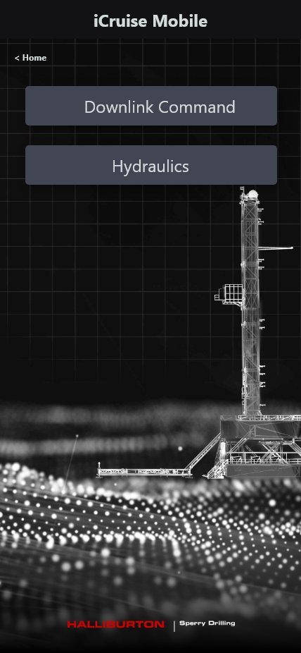
The iCruise® CX is an autonomous rotary steerable system that physically steers a drill bit through rock using pad-force steering and real-time sensor data. To tell it what to do next — change toolface angle, adjust duty cycle, enable a cruise mode — the field engineer must send a downlink: a coded series of precise flow rate and RPM changes transmitted through thousands of feet of drilling fluid. Think of it as Morse code in hydraulic pulses. The mobile app is the only way to execute that sequence correctly.
Field Mobile App
iCruise CX gave directional drilling engineers on active rig floors a mobile tool to execute precise hydraulic downlink sequences — timed flow rate and RPM changes that send encoded commands to autonomous steering tools thousands of feet below ground. A missed transition or wrong value can result in a failed command, costing hours of remediation time and tens of thousands of dollars in operational delay.

Zero Margin
Directional drilling engineers manage autonomous rotary steerable systems that guide drill bits to precise subsurface targets. Communicating commands downhole requires encoding instructions as specific flow rate and RPM changes in precise timed sequences — a process previously done with paper runsheets, mental math, and verbal coordination. Any error in timing, value, or sequence means the command doesn't register.
to Production UI
The process began with deep SME immersion — sessions with directional drilling engineers and Halliburton's Sperry Drilling technical team to map the command taxonomy, transmission mechanics, and rig floor realities before a single wireframe was drawn.
SME Immersion & Domain Mapping
Facilitated sessions with Sperry Drilling engineers to map the full command taxonomy — Express and Enhanced commands — with precise parameter ranges, transmission methods, and timing constraints. Output: a complete domain model before any UI exploration.
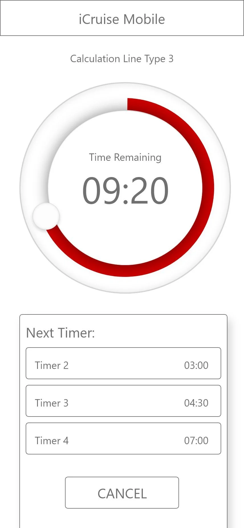
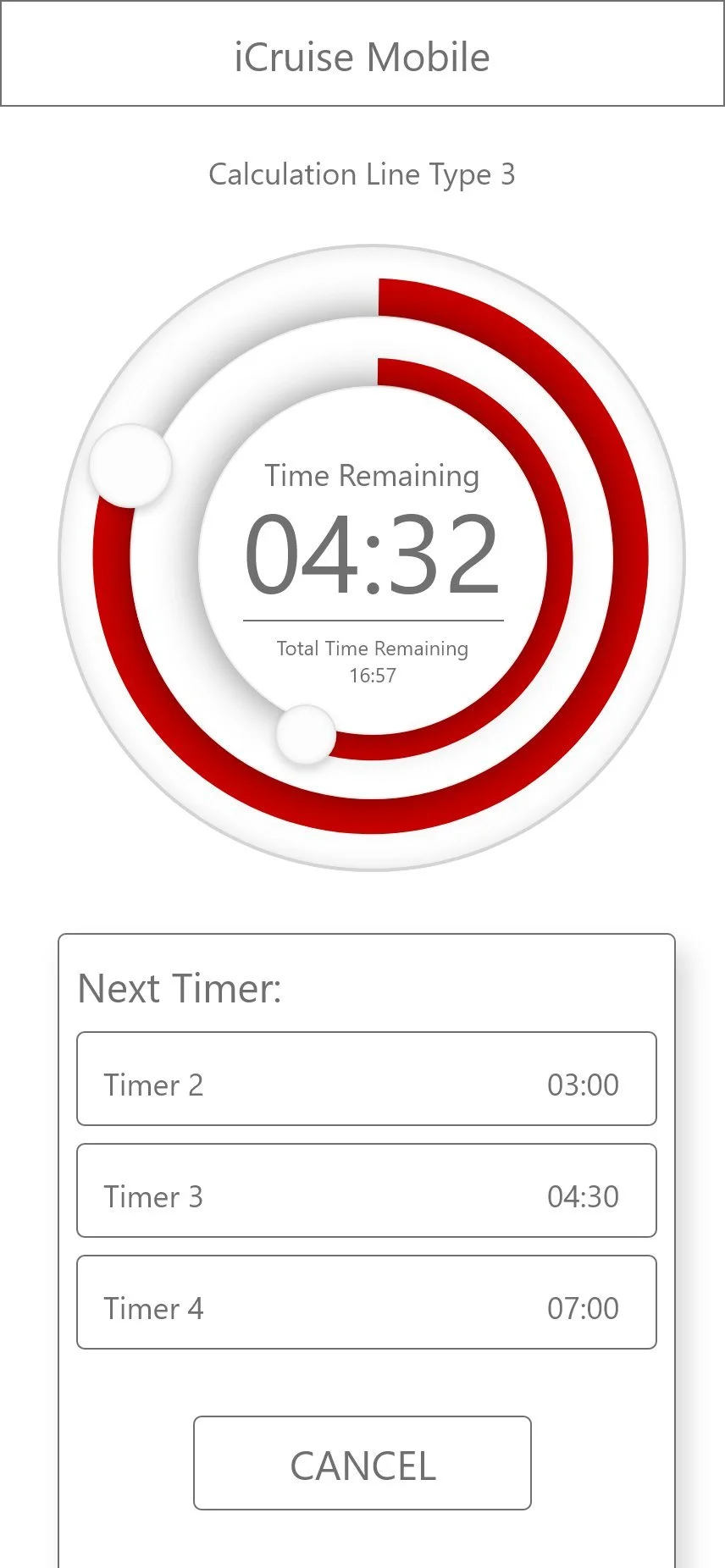
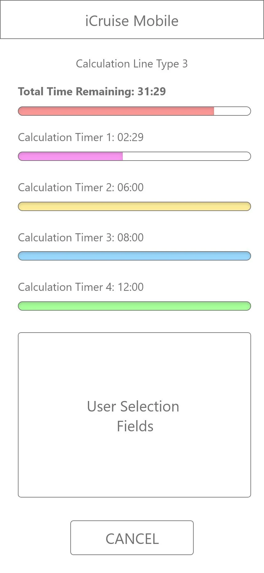
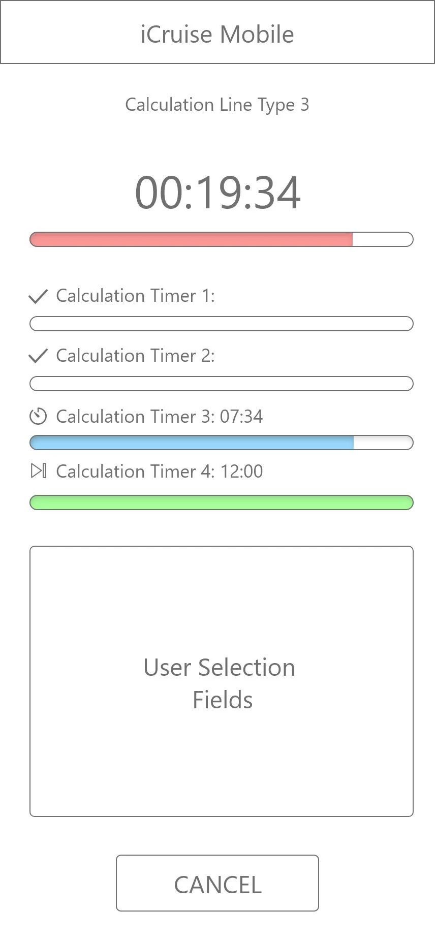
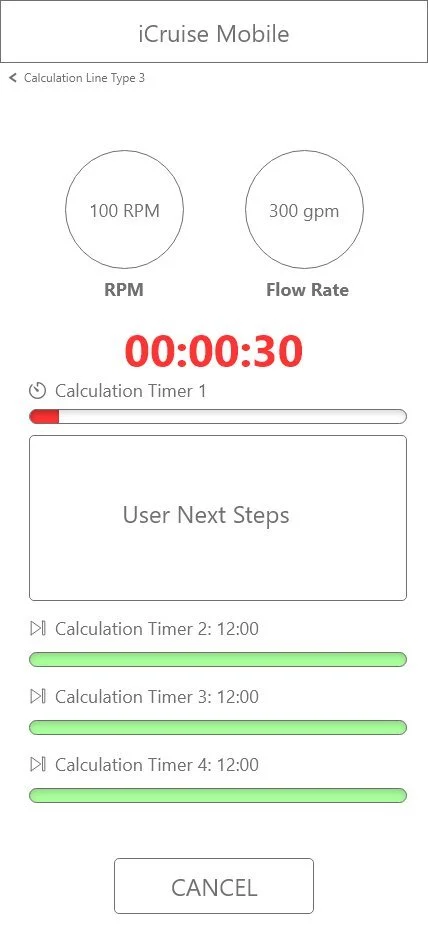
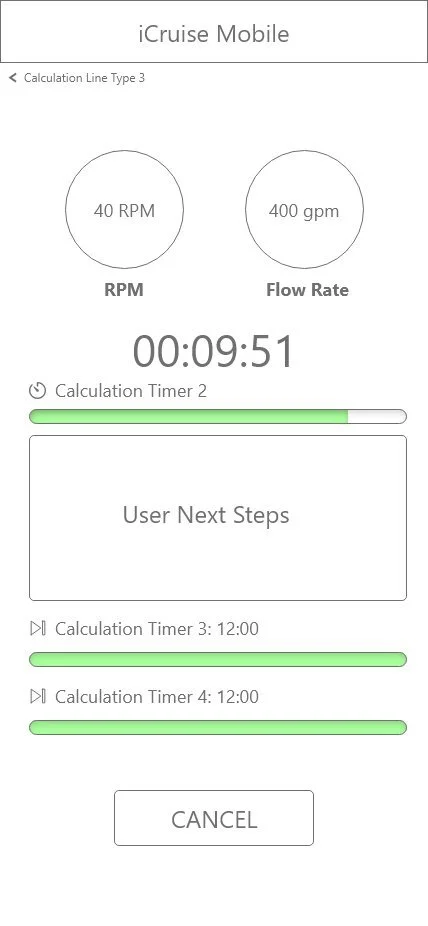
Wireframe Exploration & Timer Architecture
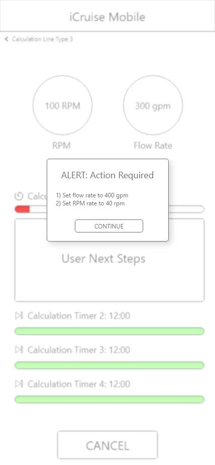
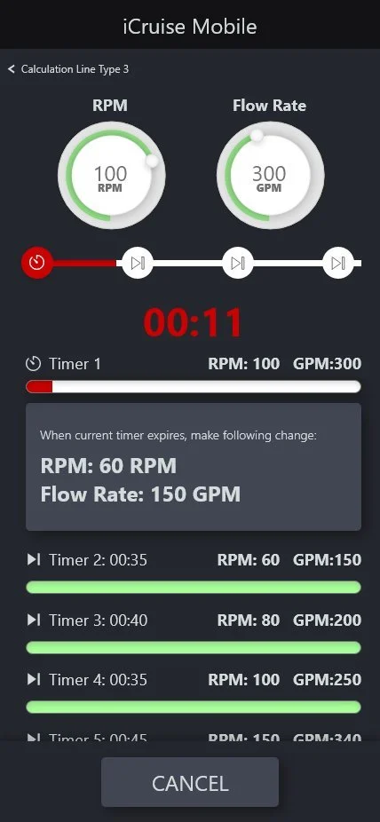
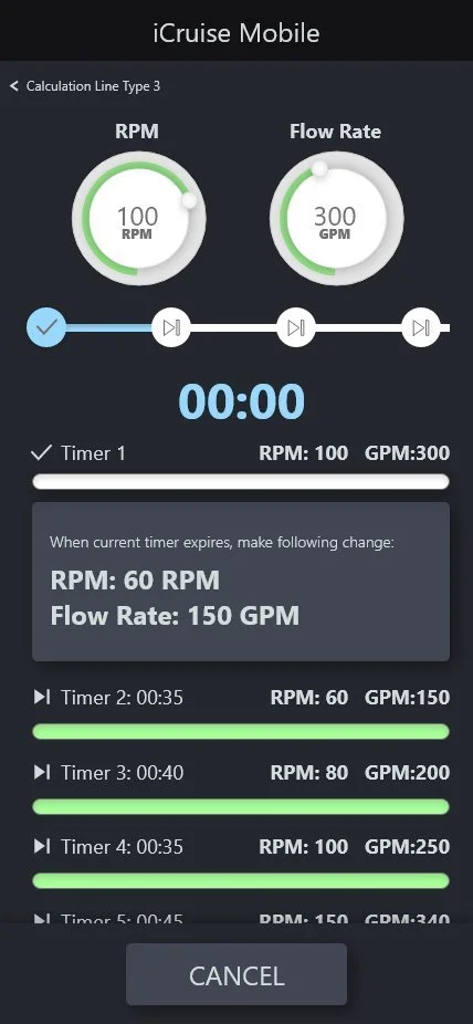
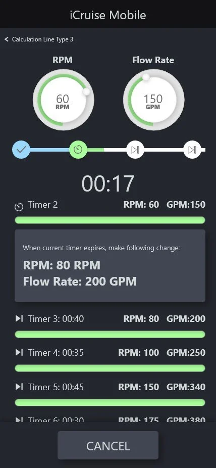
Initial wireframes tested single-ring timers, accordion lists, multi-timer progress bars, clock-face dials, and vertical gauges. V3 introduced the three-state urgency system (green → yellow → red) and the specific-value alert modal — both survived unchanged to V12.
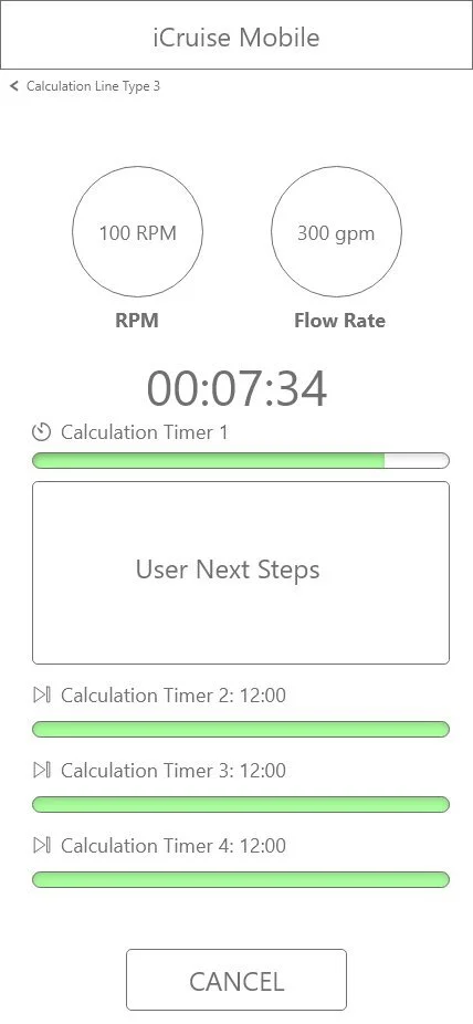
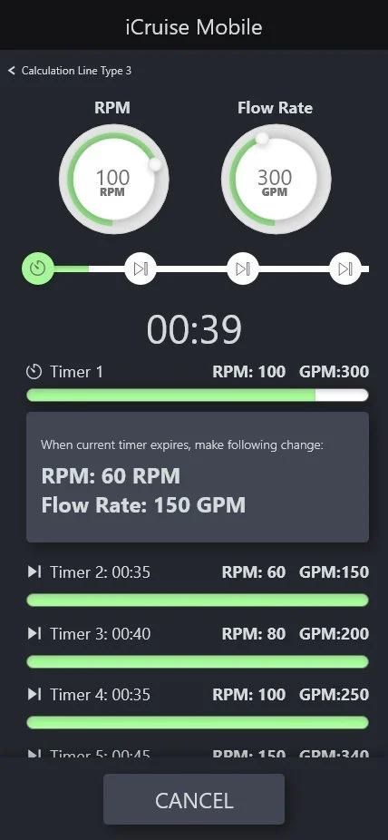
Environment-Driven Dark UI & Timeline Scrubber
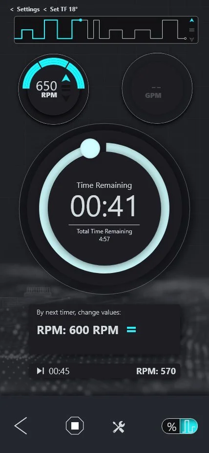
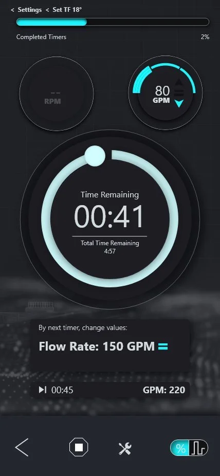
After field engineers confirmed the light theme was unreadable in direct sunlight, V5 adopted full dark mode. RPM/Flow badges became circular gauge rings. A timeline scrubber with ✓/⏱/⏭ node states was added above the countdown. The full scrollable sequence list gave engineers complete situational awareness.
Dual-Ring Timer as Hero Component
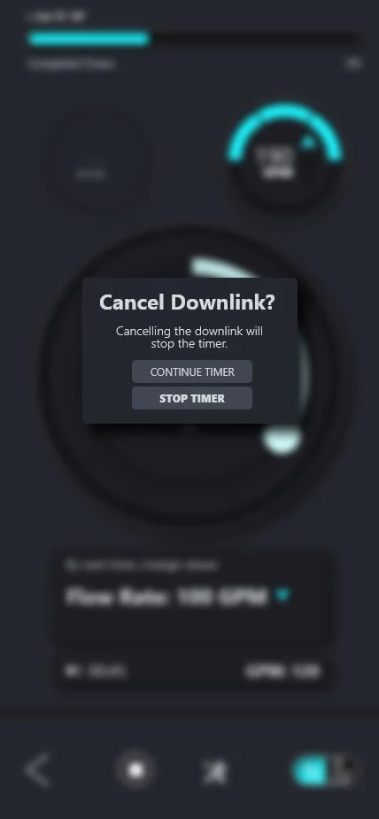
V6 was the defining leap. The glowing teal radial timer became the full-screen hero — large enough to read in peripheral vision from arm's length. The next-action card gained directional arrows (↑ teal = up, ↓ blue = down, = yellow = hold), interactive stepper overrides, and the Cancel Downlink confirmation modal.
Session Management & Safety System
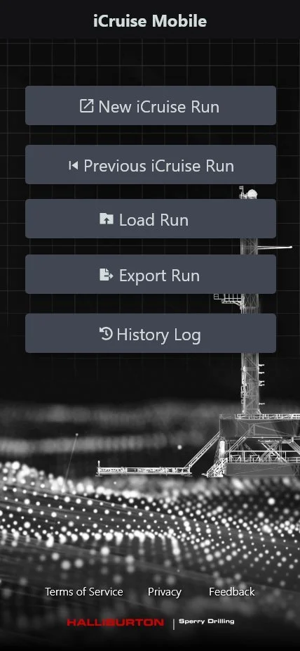
V9 completed the app architecture: branded splash with real rig photography, home hub with full session lifecycle, mandatory "Before You Start" pre-run safety modal, waveform pulse visualization, and iOS app switcher support showing the live timer when backgrounded.
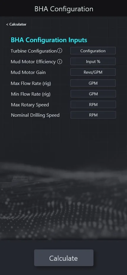
Hydraulics Calculator & Complete Feature Parity
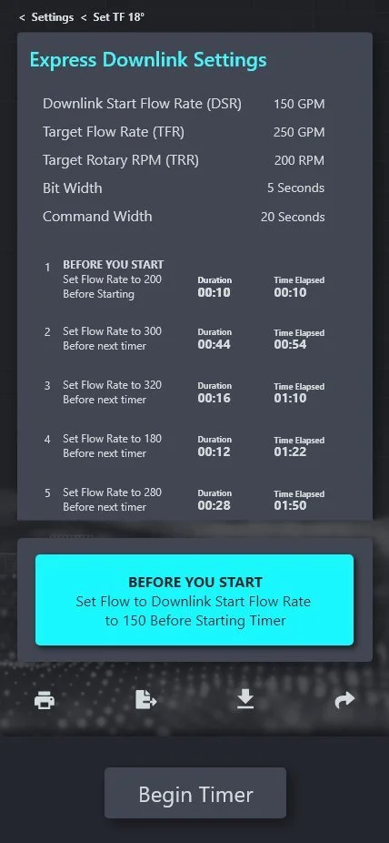
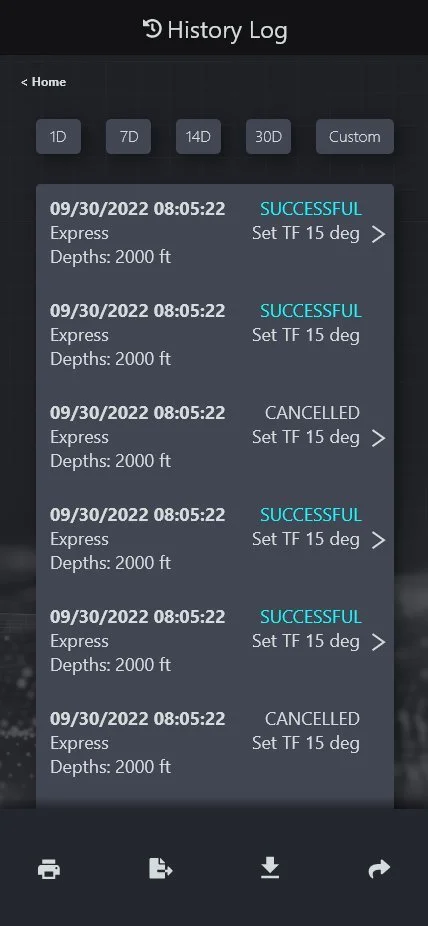
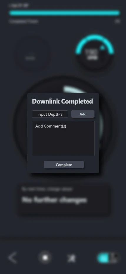
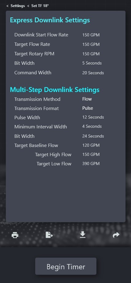
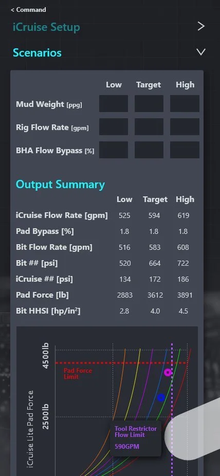
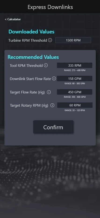
V12 delivered the Hydraulics Calculator module with BHA configuration, scenario modeling, and interactive pad force curve charts; the full History Log with time-range filtering; the Downlink Complete modal with depth and comment capture; and the Express and Multi-Step Downlinks calculators with recommended safe operating ranges.


Glanceability Under Pressure
Every design decision on the active timer screen was evaluated against a single question: can a field engineer read this in under two seconds, one-handed, in direct sunlight with a glove on?
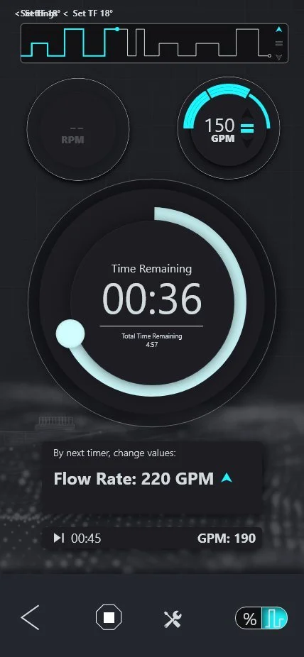
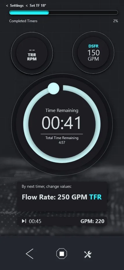
Radial Timer with Dual-Ring Progress
The large glowing radial arc communicates two time dimensions: the sweeping teal arc shows current timer progress, the inner ring tracks total sequence progress. Numerals occupy the full center at a scale readable from arm's length.
Mode-aware badges flank the timer — only the active parameter (GPM for Flow, RPM for Rotary) is fully illuminated. The inactive badge is dimmed. No decision required about which value to act on.
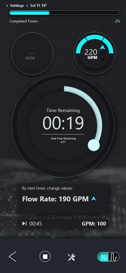
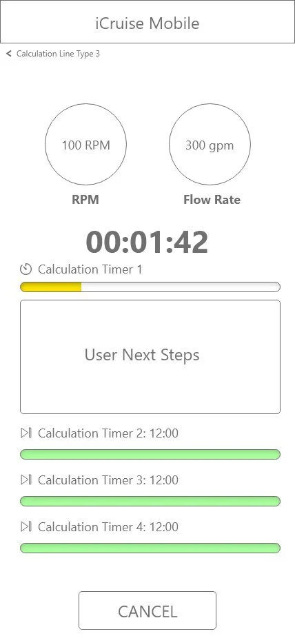
Three-State Color Escalation
As the timer approaches the action window (~1:42), the accent shifts to yellow. At 30 seconds the system goes red — numerals, progress bar, and scrubber node all shift simultaneously. An alert modal fires with exact required values.
The three states mirror industrial signaling conventions (normal / caution / critical) that field engineers already recognize — zero learning curve.
Pulse Visualization & iOS Live State
The waveform renders the downlink pulse pattern in real time, confirming the transmission signal structure. Critical for Multi-Step commands where Pulse Width, MIW, and format determine whether the tool decodes the command correctly.
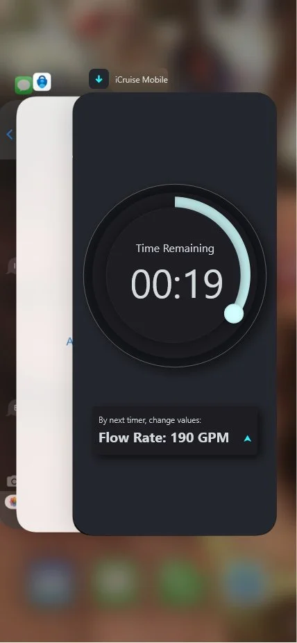
When engineers switch apps mid-downlink, the iOS app switcher card shows the live countdown and next-action card. The timer never pauses. Critical information never disappears.
Designed for Context
One Coherent System
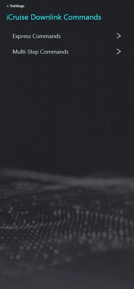
The command architecture required surfacing two fundamentally different mental models — Express (fast, minimal input) and Multi-Step (precision, configurable) — without forcing engineers to navigate a confusing split at every session.
Simplified Command Path
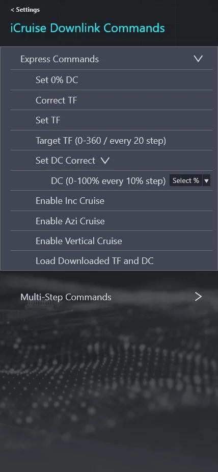
Express Commands cover the most common operations: Set 0% DC, Correct TF, Set TF (0–360° in 20° steps), Set DC Correct (0–100% in 10% steps), Enable Cruise modes, Load Downloaded TF and DC. Accordion list allows inline parameter configuration.
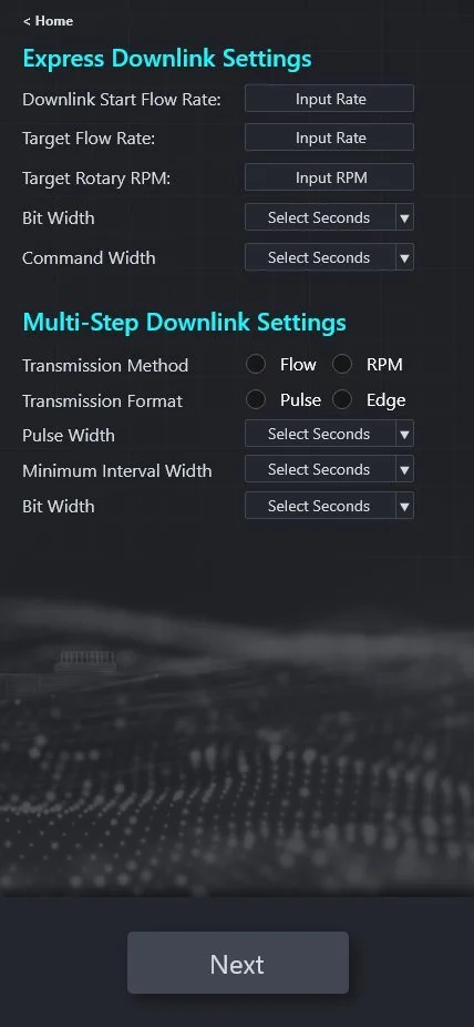
Precision Configuration
Multi-Step commands expose the full parameter surface: Set TF+DC (0–354° in 6° steps), Correct TF (±5/10/20/30°), Correct Inc/Azi (0 to ±1.0° symmetric), Set Cruise modes with independent Gain (0–7), and Enable Manual Downlinks with custom MIW and Bit Width.
Out of the Way
Pre-Job Engineering
Beyond downlink execution, V12 delivered a full Hydraulics Calculator module — giving engineers the ability to run complete hydraulic scenario modeling directly in the app, eliminating the need for separate desktop tools.
Full Hydraulic Scenario Modeling
The module consists of four sequential sections: Job Information, iCruise Setup (Tool Size, Hole Size, Restrictor, Bit TFA), Scenarios (Mud Weight, Rig Flow Rate, BHA Flow Bypass across Low/Target/High), and Outputs.
The Output section generates a complete hydraulic table across all three scenario bands alongside an interactive Pad Force curve chart with safety limit overlay markers.
& Rationale
Dark Theme Over Light
Field testing confirmed the light theme was nearly unreadable in direct sunlight. The shift to dark dramatically improved outdoor contrast and allowed the teal accent to glow with maximum visual impact.
Radial Timer Over Progress Bar
Multi-timer horizontal bars (V1) required focused reading. A large radial timer is readable in peripheral vision — an engineer can glance and instantly perceive time remaining without direct focus.
Persistent Action Card
Waiting until threshold to surface the required action creates a last-second scramble. The persistent card with specific values keeps engineers mentally prepared throughout the current timer.
Mode-Aware Parameter Display
Showing both badges at full contrast created confusion about which value to act on. Dimming the inactive badge and illuminating only the mode-relevant one removes the decision entirely.
Inline Direction Indicators
↑ teal = ramp up, ↓ blue = ramp down, = yellow = hold. Icon + color communicates directionality faster and more reliably than words in a loud, high-urgency environment.
Cancel Confirmation Modal
Cancelling mid-sequence wastes the command window and requires a full restart. Two-action confirmation prevents accidental cancellation while keeping the recovery path equally accessible.
Parameter Architecture
The UI design was anchored by a precise domain model — the SME-defined command taxonomy that governed every input control, value range, and configuration screen in the application.
| Command | Parameter Range |
|---|---|
| Set 0% DC | No input — single-action command |
| Correct TF | No input — single-action correction |
| Set TF | 0–360° / every 20° step |
| Set DC Correct | 0–100% / every 10% step |
| Enable Inc Cruise | Toggle — no additional input |
| Enable Azi Cruise | Toggle — no additional input |
| Enable Vertical Cruise | Toggle — no additional input |
| Load DL TF & DC | Loads pre-configured values |
| Command | Parameter Range |
|---|---|
| Set TF+DC | TF: 0–354° in 6° steps; DC: 0–100% in 10% steps |
| Correct TF | ±5, ±10, ±20, ±30° |
| Correct DC | ±10, ±20, ±30% |
| Correct Inc | 0, ±0.1, ±0.2, ±0.5, ±0.75, ±1.0° |
| Correct Azi | Same symmetric range as Inc |
| Set Cruise Inc | Gain 0–7; Adj ±0.2, ±0.5, ±1.0, ±2.0° |
| Set Cruise Inc/Azi | Gain 0–7; Adj ±0.2, ±0.5, ±1.0, ±1.5° |
| Enable Manual DLs | New MIW; New BW |
| Parameter | Options / Range |
|---|---|
| Method | Flow rate modulation · RPM modulation |
| Format | Pulse · Edge |
| Pulse Width | Configurable in seconds |
| Min Interval Width | Configurable in seconds |
| Bit Width | Configurable in seconds |
| Target Baseline Flow | GPM — calculated by Express DL Calculator |
| Target High / Low Flow | GPM — calculated with recommended safe range |
iCruise CX represented Halliburton Sperry Drilling's first dedicated mobile application for directional drilling command execution — a greenfield product that translated a paper-based, error-prone field process into a structured, error-preventive digital workflow.